Robot serial number:20225300304
Passwords:
- safety: 0000


Robot serial number:20225300304
Passwords:
Update 17.03.2023: Added instructions for dealing with ESP32-S2 hardware.
This guide should enable you to install ROS 2 Humble on a fresh Ubuntu installation and compile micro-ROS for ESP32 using automated scripts. Additionally, I added the section for running a docker container, so the guide should work on almost any Linux based system which has docker installed.
Section Part II is added, that includes instructions for compiling micro-ROS for ESP32-S2 based devices. The problem here is, that the standard micro-ROS distribution mentioned in the official tutorial does not ship with a current espressif-idf that supports ESP32-S2 boards. It seems like you need an esp-idf above version 4.4.
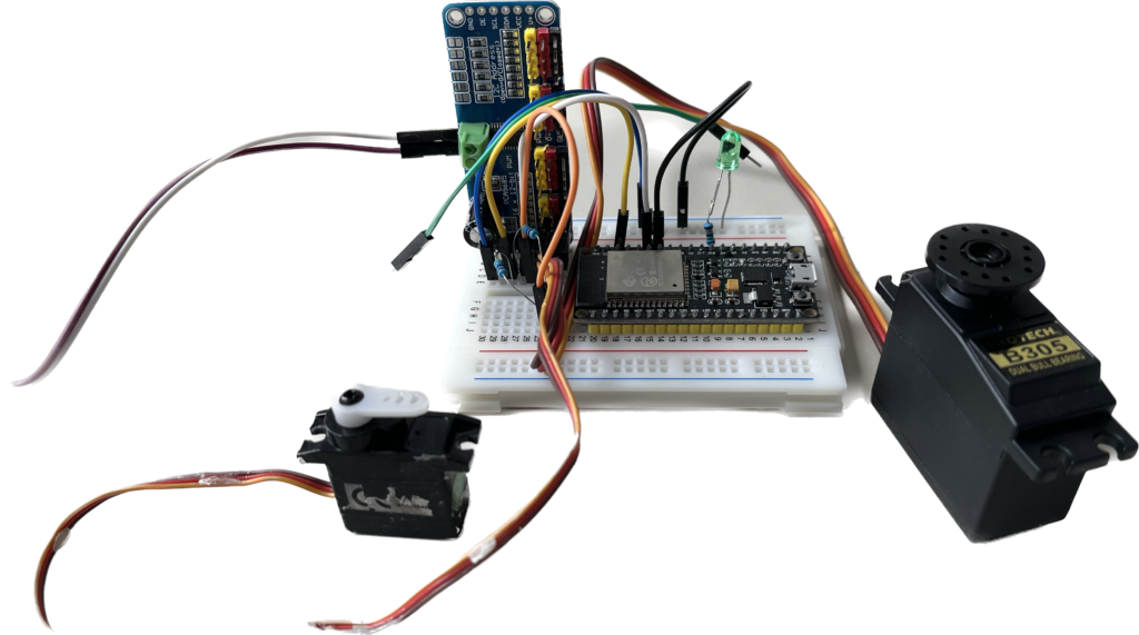
We will use the FreeRTOS implementation for ESP32. Steps will lead to automatic compilation of provided “app” for the ESP32 and connect it to the ROS humble environment.
docker run -it --net=host -v /dev:/dev --privileged ros:humble
# Source the ROS 2 installation
source /opt/ros/$ROS_DISTRO/setup.bash

# Create a workspace and download the micro-ROS tools
mkdir microros_ws
cd microros_ws
git clone -b $ROS_DISTRO https://github.com/micro-ROS/micro_ros_setup.git src/micro_ros_setup

# Update dependencies using rosdep
sudo apt update && rosdep update
rosdep install --from-paths src --ignore-src -y

# Install pip
sudo apt-get install python3-pip

# Build micro-ROS tools and source them
colcon build
source install/local_setup.bash
Pay attention to use platform “esp32”
# Create step
ros2 run micro_ros_setup create_firmware_ws.sh freertos esp32
# Configure step with ping_pong app and serial transport
ros2 run micro_ros_setup configure_firmware.sh ping_pong --transport serial
# Build step
ros2 run micro_ros_setup build_firmware.sh
Connect esp32 via USB cable or appropriate interface. Most likely all the esp32 dev-boards offer USB connection and will be recognized as ttyUSB0 (USB serial device). In this step, the flash program will find the right port for you automatically.
Caveat ahead: If you are not running the process as root user (which is the recommended approach anyways), you must make sure that you have write permissions on the /dev/ttyUSB0 device. That can be established like follows:
sudo chown $USER /dev/ttyUSB0Depending on your configuration, it is possible that you need to adapt above command. By running the flash step you will most likely see which device you need to use when the process exits with an error 🙂
# Flash step
ros2 run micro_ros_setup flash_firmware.sh
To make sure everything is working, disconnect the device after the flashing process is done or just reset it via the enable button (EN).
# Download micro-ROS-Agent packages
ros2 run micro_ros_setup create_agent_ws.sh
# Build step
ros2 run micro_ros_setup build_agent.sh
source install/local_setup.bash
# Run a micro-ROS agent
ros2 run micro_ros_agent micro_ros_agent serial --dev [device]
Replace [device] with your serial connection. Again, remember to choose the /dev/ttyUSB* device selected in the flash step. To avoid searching for the correct serial port in the future, you can also find out the discrete device identifier by having a look at this command’s output:
ls /dev/serial/by-id/*At this point, the micro-ROS app is built and flashed and the board is connected to a micro-ROS agent. We now want to check that everything is working.
Open a new command line. We are going to listen to the ping topic with ROS 2 to check whether the micro-ROS Ping Pong node is correctly publishing the expected pings:
source /opt/ros/$ROS_DISTRO/setup.bash

# Subscribe to micro-ROS ping topic
ros2 topic echo /microROS/ping
You should see the topic messages published by the Ping Pong node every 5 seconds:
user@user:~$ ros2 topic echo /microROS/ping
stamp:
  sec: 20
  nanosec: 867000000
frame_id: '1344887256_1085377743'
---
stamp:
  sec: 25
  nanosec: 942000000
frame_id: '730417256_1085377743'
---
At this point, we know that our micro-ROS app is publishing pings. Let’s check if it also answers to someone else’s pings. If this works, it’ll publish a pong.
So, first of all, let’s subscribe with ROS 2 to the pong topic from a new shell (notice that initially we don’t expect to receive any pong, since none has been sent yet):
source /opt/ros/$ROS_DISTRO/setup.bash

# Subscribe to micro-ROS pong topic
ros2 topic echo /microROS/pong
And now, let’s publish a fake_ping with ROS 2 from yet another command line:
source /opt/ros/$ROS_DISTRO/setup.bash

# Send a fake ping
ros2 topic pub --once /microROS/ping std_msgs/msg/Header '{frame_id: "fake_ping"}'
Now, we should see this fake_ping in the ping subscriber console, along with the board’s pings:
user@user:~$ ros2 topic echo /microROS/ping
stamp:
  sec: 0
  nanosec: 0
frame_id: fake_ping
---
stamp:
  sec: 305
  nanosec: 973000000
frame_id: '451230256_1085377743'
---
stamp:
  sec: 310
  nanosec: 957000000
frame_id: '2084670932_1085377743'
---
Also, we expect that, because of having received the fake_ping, the micro-ROS pong publisher will answer with a pong. As a consequence, in the pong subscriber console, we should see the board’s answer to our fake_ping:
user@user:~$ ros2 topic echo /microROS/pong
stamp:
  sec: 0
  nanosec: 0
frame_id: fake_ping
--
Source: https://micro.ros.org/docs/tutorials/core/first_application_rtos/freertos/
In this case, I would advise anybody to use a docker container for the build process, as there is a bunch of dependencies installed in the process that might interfere with your currently running setup.
Make a new project directory and cd into it.
cd ~
mkdir microros
cd microrosRun a docker container that already includes needed dependencies, for instance a current version of esp-idf.
docker run -it --rm --name micro_ros --volume="/etc/timezone:/etc/timezone:ro" -v $(pwd):/micro_ros -v /dev:/dev --privileged --workdir /micro_ros microros/esp-idf-microros:latest /bin/bashSetup your container:
Source the micro-ROS component for the esp32 platform.
git clone https://github.com/micro-ROS/micro_ros_espidf_component.git
pip3 install catkin_pkg lark-parser empy colcon-common-extensionsSelect an example project and configure it for esp32-s2. As you can see, it should also be possible to configure the firmware for esp32-s3 and -c3 models. But I have not tested that yet.
cd examples/int32_publisher
# Set target board [esp32|esp32s2|esp32s3|esp32c3]
idf.py set-target esp32s2Use menuconfig to insert the WiFi Credentials and specific settings.
idf.py menuconfig
# Set your micro-ROS configuration and WiFi credentials under micro-ROS SettingsBuild your micro-ROS application and flash it to your esp32-s2 device. Additionally, start a monitoring process via serial console to see if there are any errors with the device. You will probably see some errors after connecting to the network, as the corresponding micro-ROS agent is not running on the computer yet.
idf.py build
idf.py flash
idf.py monitorStart a micro-ROS agent container to connect to your newly set-up esp node.
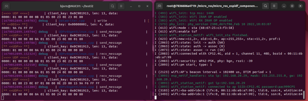
# UDPv4 micro-ROS Agent
docker run -it --rm --net=host microros/micro-ros-agent:humble udp4 --port 8888 -v6
Now you should see something similar to this:
In the end, this gives you the tools needed to compile the firmware for a ESP32-S2 based device. After exiting the build-container, the generated files are still available under provided project directory on your computer.
Source: https://github.com/micro-ROS/micro_ros_espidf_component