image_pdfimage_print

Meeting on the 5th, October 2022

Location: Chair of CPS

Date & Time: 5th Oct 2022

Participants: Univ.-Prof. Dr. Elmar Rueckert, DI Nikolaus Feith, BSc


Agenda

  1.  Update and more detailed definition of the the project
  2. Master thesis GNN for Motion Planning
  3. Next steps

Top 1: Update and more detailed definition of the the project

  • Last week, work continued on the ROS framework. There were problems with the inverse kinematics solver, because the Jaccobian matrix is generated incorrectly by the used Python packages. For the time being we will only work with the Impedance Effort Controller from Franka.
  • Furthermore, the CPS Lecture Repository was created and the CoppeliaSim simulation file and the Python script to operate it were programmed. In addition, a description of how to work with the simulation was written.
  • Further details were discussed in the ROS framework. The framework should work with different simulation programs (CoppeliaSim, IssacSim). The goal is to implement an RL environment, so that an initial solution can be given with the pen on the tablet. This initial solution (trajectory) should be used as motion primitives for the RL. The weights of the MPs are to be learned. Furthermore, it should be possible to manipulate the MP in real time, so that the user can further refine the trajectory in the learning process. The Gym library will be used for the evaluation. For the experiment, the lathe and the milling machine will be used (button press, lever operation, etc.). 
  • A research on related work shall be done, especially if such systems/frameworks have already been developed with ROS2. 
  • Not all sensors, HW devices, robots, etc. need to be implemented by myself, but there need to be a template for the different parts, so every one can extend the frame work.
  • XBox Controller: The Xbox controller is to be used for teleoperation for the robots, as well as the possibility for recording experiments should be implemented. E.g. fixation of a configuration, so that the same experiment can be recorded again and again from the same configuration or the possibility to separate a recording by pressing a button, so that the experiment has to be started only once and not for every run again.

Top 2: Master thesis GNN for Motion Planning

  1. Definition of a master thesis with the topic: GNN for Motion Planning
  2. https://github.com/rainorangelemon/gnn-motion-planning
  3. https://rainorangelemon.github.io/NeurIPS2021/paper.pdf

Top 3: Next Steps

  1. ROS
  2. ROS2
  3. Tablett for shared control (user correction)
  4. Hardware: which hardware is needed to work with the Framework

Meeting on the 28th, September 2022

Meeting on the 13th of August 2021

Location: Chair of CPS

Date & Time: 13th Aug. 2021, 9 am to 9:30 am

Participants: Univ.-Prof. Dr. Elmar Rueckert, Nikolaus Feith, BSc


Agenda

  1.  Project definition
  2. Update and next steps

Top 1: Project definition

Three main projects:

  1. ROS CPS Framework
  2. Reimplementation GNN for Motion Planning
  3. Literature research

The development of a ROS/ROS2 framework to control the CPS robots.
Furthermore, an interface for the use of a tablet is to be programmed in ROS2. On the tablet trajectories can be designed (movement primitives) which can be changed directly with the pen. For this a simple GUI is needed for the display and manipulation of trajectories as well as the display of the robot in 3D in real time. As well as the use of the CPS glove.
This program is intended to be an application of active learning methods, especially for shared and preference learning.
Finally, a connection will be made to the methods of Probabilistic Inference, see GNN for Motion Planning.
If possible, a comprehensive platform including ROS Mobile should be developed.

Top 2: Update and next steps

  1. Update: 
    1. Last week a Joint Effort Controller was implemented and tested in Gazebo. The application in combination with the inverse solvers of the robotic toolbox was tested, but still leads to errors in the control.
    2. Literature research: Bishop
  2. Next steps:
    1. In the coming week, these errors will be corrected and the tests on the Franka robot arm will start.
    2. Literature research: finish Bishop

How to install Python and PyCharm

This tutorial explains how to install the basic Python environment for the Lecture Maschine Learning. This course requires a Python version >= 3.8 and PyCharm as IDE. In case you are using another operating system you can find some links at the end of this wiki post.

Download and Installation of Python

To program with Python you need a current Python version, which can be downloaded from the following website: Python. Basically every version after 3.8 can be used, quite new versions can still have bugs now and then, furthermore some packages are not yet transferred to the newest version, therefore 3.9 is recommended.

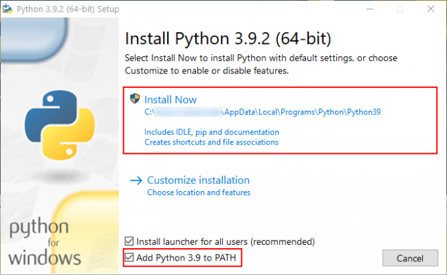
After the download, the program must now be installed. It is important that Python is added to the PATH, otherwise this step must be done manually. This is accomplished by selecting the “Add Python 3.9 to PATH” checkbox. Now Python is installed and the IDE “PyCharm” can be downloaded. 

Installation of PyCharm

To install PyCharm visit the jetbrains website and follow the instructions. We recommend the Professional version, to get the license for it you need to create an account on Jetbrains and log in to the program after the installation. 

Links

How To fix the Robot Hand (Overheat Error)

Signs of an Overheat Error

Two signs occur when the overheating error is present:

1) Only the red lamp on top of the robot hand is light up continuously.
2) The ROS Terminal (running the roslaunch rh8d start_rh8d.launch programm) displays “Overheat Error”. In the picture below the error message for servo #38 is displayed.

Needed Resources

  1.  Download the TSBAdvanced Loader binary from github.
  2.  Download the RH8D Fix folder (so far we have only the fixes for Servo #33, #35 and #38, if you need a different one please talk to Prof. Rückert).

How the fix works

  1. Connect the robot hand via the micro USB connector on the side of the hand to a Windows computer.
  2. Plug in the power supply of the robot hand.
  3. Open a Terminal on the Windows computer.
  4. Move to the directory were you unziped the “RH8D Fix.zip” files.
  5. Check the COM connection to the robot hand in the devices manager (i.e. COM4).
  6. Now enter the bridge mode with the terminal command : “tsbloader_adv.exe -port=[the Virtual Serial port number/id you determined in point 1] -seederos=bron” (replace the [the Virtual Serial port number/id you determined in point 1] with i.e. COM4.
  7.  Depending on the servo motor, the corresponding pwd must now be used. Servo #31 = A; Servo #32 = B; … Servo #38 = H.
  8. To reset the faulty temperature sensor of the corresponding servo motor use the following command: “tsbloader_adv.exe -port=[YOUR COMM PORT] -prewait=2000 -pwd=[SERVO-PWD] -eop=ewv -efile=[RESET FILE FOR THE SERVO] -baud=33333”
  9. If there are more than one errors, fix only one at a time!
  10.  After completion use the command: “tsbloader_adv.exe -port=[the Virtual Serial port number/id you determined in point 1] -seederos=broff” to leave the bridge mode.
  11. Afterwards reboot the hand (replug the power supply and disconnect the micro USB cable). After booting all three lamps should light again. Otherwise contact the support of seed robotics via email: support@seedrobotics.com

Sources

CoppeliaSim Tutorial

This tutorial describes the usage of the program CoppeliaSim. In particular, the use of the software in the context of the course “Cyber-Physical-Systems” is discussed.

Download and setup of the program

CoppeliaSim can be downloaded from this website. Furthermore, the Python package “msgpack” must be downloaded via pip. Depending on your operating system, different steps are required after the installation.

Windows 10

For Windows 10, no further installation steps are necessary. However, to use the B0-based remote API, some .dll files must be available in the working directory. These can be found in the installation folder of CoppeliaSim. To shorten the search for the files, you can find all the required files in the GitHub project linked below.

Ubuntu 20.04

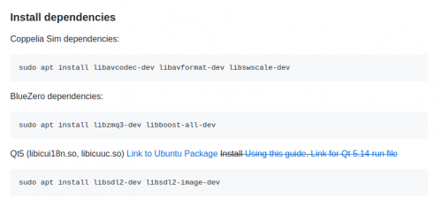
Before CoppeliaSim can be started, dependencies for the BlueZero API have to be installed. To accomplish that follow the instructions bellow.

Bildschirmfoto von 2021-11-16 16-53-35

In contrast to Windows, CoppeliaSim must be started from the terminal on Ubuntu. To do this, right-click on the unpacked folder and select the option “Open in Terminal”. Then enter the following command “./coppeliaSim.sh”. After confirming with the Enter key, CoppeliaSim starts. To use the B0-based remote API, the file “libb0.so” must be available in the working directory. For some simulations, additional files must be added in the same directory, these can also be found in the GitHub project linked below.

CoppeliaSim and B0-based remote API - Python Client

As described above, depending on the operating system, .dll and .so files need to be added to the workspace. Besides the operating system specific files, the Python scripts “b0.py” and “b0RemoteApi.py” must be present in the working directory. These files can be found in the installation folder or in the GitHub project. For the task of the course, the following two applications are most important: actuation, sensing. Sample code for actuation and sensing can also be found in the GitHub project. In the following section, their application is briefly discussed. 

Actuation

Using the API, Two movement modes are implemented in the provided scene “scene_with_pandas.ttt”. These are used with the method “simxCallScriptFunction” in Python because they are programmed as a function in the simulation file. The following modes are available:

  • – pts: In this mode, the angular positions of the joints and the corresponding time are passed to the simulation as a list (all intermediate points are interpolated). This mode is important for control tasks and if the inverse and forward kinematics have been developed by the user.
  • mov: In the “mov”-mode, the positions and speeds of intermediate points are transferred to the simulation. The inverse kinematics of Reflexxes Motion Library type II or IV is used in this mode.

Sensing

At the beginning, the object handles of the observed objects must be determined, this is done with the help of the method “simxGetObjectHandle”. To execute this method you need a so-called topic, more about this down below. Since “simxGetObjectHandle” only needs to be executed once, and only at the beginning or before the simulation, the topic “simxServiceCall” is used.

Afterwards, the joint angles or joint positions can be streamed with the help of the method “simxGetJointPosition” and the position of the end effector with “simxGetObjectPosition”. To achieve this, a callback function is needed for each angle or for the coordinates (one for each xyz triplet). These callback functions are called cyclically and can be used, for example, to store the angles in an array. Finally, it must be noted that the sensor data should always be saved with their time, otherwise no meaningful calculations or diagrams can be made.

As with the actuation, sample codes are available in the GitHub project.

Links

What are the thesis guidelines

Word processor

We believe that the best way to write a technical paper is by using LaTeX. Therefore, we provide a LaTeX template for you which you can download at the end of this page. Furthermore, we recommend the lecture notes form Prof. O’Leary’s lecture “Engineering and Scientific Documentation” for a basic introduction in writing technical papers and LaTeX. At this point we would like to thank Prof. O’Leary for allowing us to link to his lecture notes.

Text structure

There are no general guidelines for text structure. Since each thesis is unique, the structure will be discussed in detail with the supervisor. The same applies to the scope of the paper. A basic setup is nevertheless available in the LaTeX-template.

Language

Basically, you can write your thesis in German or English. However, you have to coordinate this with your supervisor, since we also have international staff at our chair who support your work and can do this better in English.

Realization of the thesis

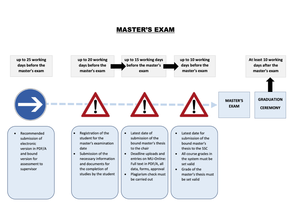
For Bachelor’s theses, the total duration of the work should be approximately 3 months and concludes with the presentation of the thesis to the chair staff. Master’s theses should take about 6 months. Within the scope of the thesis, you have to make an interim presentation at the chair, as well as a final presentation within the scope of the master’s examination. More details can be found in the article “Completion of the master’s program”.


Template and Script

Master Thesis Process Workflow

Basic Workstation Build

The basic build of a workstation computer is described in the following entry:

Hardware Components

  • Mainboard: Gigabyte Z590 D
  • Processor: Intel Core i9-10850K
  • RAM: AEGIS DDR4 F4-3000C16D-32GISB
  • Graphics Card: NVIDIA Geforce GT710
  • SSD: VIPER VPN100 PCIe m.2 SSD 512GB

Standard Software Package on Workstation

You can find a backup of the standard software package at the technicans repository. Don’t use the backup but clone it. This software package includes the following software:

  • OS: Ubuntu 20.04
  • Driver: Nvidia GPU
  • Office and Latex
    • WPS Office
    • Texmaker – LaTeX Editor
    • Tex Live – LaTeX Distribution
    • Mailspring
  • Browser
    • Firefox
    • Chrome
  • Programming
    • Visual Studio Code
    • Pycharm community
    • Matlab 2020b
    • Github Desktop
    • Python 3.8 – included with Ubuntu 20.04
    • Arduino IDE
  • Video and Images
    • VLC Video Player
    • Inkscape
  • Conference Tools
    • Webex
    • Skype
    • Zoom
  • Cloud Storage and Password Management
    • Dropbox
    • Keypassx
  • Process Manager
    • htop
  • ROS:
    • ROS is not included in the standard software package due to employee preferences – some prefare ROS 1 other ROS 2.

How to write a thesis at the chair of cyber-physical systems

What is a bachelor or a master thesis?

At the end of your bachelor or master studies you have to write a thesis. In case of the bachelor’s study programme your workload should be around 180 to 200 netto work hours (7.5 ECTS credits) and your master’s thesis workload should be around 600 to 650 netto work hours (25 ECTS credits). In these theses, you as a student should independently research the topic and prove your scientific problem-solving strategies. To solve this difficult task, we will help you with our expertise.

What are the requirements to write a thesis?

The bachelor’s programme at MUL requires that you have already completed the courses of the first four semesters to start your thesis. The prerequisite for writing your master’s thesis is to be enrolled in a master’s programme.

How do I get a thesis at the chair of cyber-physical systems?

First, you can check our homepage to see if you find a topic that interests you. If this is not the case, you can contact our chair and propose your own topic. In any case, you should ask for a personal appointment at the secretary’s office so that possible questions or topics can be discussed.

Important Information

If you want to write your thesis at the chair of cyber-physical systems, do not start writing the thesis until it is approved by the chair. Otherwise, it is possible that your topic can change during writing.
At University of Leoben we have a guideline for good scientific practice, therefore the university wants you to stick to this practice.
Finally, the chair of cyber-physical systems has an internal guideline for the implementation of a thesis. More about this in our wiki article on thesis guidelines.


Meeting on the 13th of August 2021

Meeting on the 13th of August 2021

Location: Chair of CPS

Date & Time: 13th Aug. 2021, 9 am to 9:30 am

Participants: Univ.-Prof. Dr. Elmar RueckertNikolaus Feith, BSc


Agenda

  1.  Concept for master thesis

Top 1: Organisational Update

Thema: Probabilistic Motion planning

Goal: Model based planning via message passing and Kalman Smoothing(KS)
(planning as Inference)

Experiments:

1) 1-D cart+sensor-simulation – proof of concept( physics+dynamics sim, planning and KS)
2) 2-D robot sim as kinematic chain with beam sensor and orientations constraints
3) CopelliaSim (+ ROS with own planning algorithm)
4) Franka Panda

Roadmap:
1) Toy task – 1-D physics and dynamics simulation of the cart
2) Toy task – baseline planning (positioning via Euler-distance)
3) Toy task – implementing Kalman Smoother
4) Toy task 2 – 2-D Robot arm (2 links with endeffector)
5) Toy task 2 – Planning in Cartesian space – Inverse kinematic + Kalman Smoother
6) CoppeliaSim of Franka with 3-D printed tool – simple tool guiding (orientation!!)
7) Real world testing with Franka
optional: ROS Implementation of the planning algoritm

Literature: Bayesian Modeling and Machine Learning (Chapter 23, p 493 – KS)

B.Sc. Thesis: Leander Busch on Learning Motion Models for Local Path Planning Strategies

Supervisors: Elmar Rückert, Nils Rottmann

Finished: 15.Februar.2021

Abstract

The Segway Loomo is a self-balancing segway robot, which is constantly balanced by an internal control system. A local path planning strategy was developed in advance for this robot. For local path planning, a motion model of the robot is needed to determine the effect of velocity commands on the robot’s pose. In the implemented local path planner, a simple motion model of the robot is used, which does not model the effect of the segway robot’s internal control on its motion. In this work, it was investigated whether a more accurate motion model for the Segway Loomo robot can be learned by using artificial neural networks to improve the local path planning for this robot. For this purpose, different architectures of feedforward networks were tested. The neural networks were trained and evaluated using recorded motion data of the segway robot. The best learned model was validated by using a standard differential drive motion model as a reference. For the validation of the learned model, the accuracy of both motion models was examined on the recorded motion data. On average, the learned model is 59.48 % more accurate in determining the position of the robot at the next time step and 24.61 % more accurate in determining the new orientation of the robot than the differential drive motion model.

Thesis